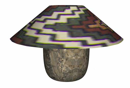
Below is a sample drawing showing 2 different revolved
objects (lamp and lampshade). It will also be your goal in this lesson to duplicate
similar objects.
So far you've only worked with very basic blocks. Suppose
that you need to draw something other than a rectangular
cube. You did some new shapes in the previous lesson while extruding and lofting. AutoCAD gives you two commands for those times
when you need to draw cylindrical objects. One (revsurf)
will give you a complex model comprised of a 3-D surface
made up of many facets. The other (revolve) will
give you a solid object. The method that you use will once
again depend on what you need it for. Take a look at
the lamp on this page. This is an example of two different
types of objects requiring two types of object construction.
The lampshade is a 'hollow' object. Essentially it's
just a surface. The lamp base is a solid object. The revsurf command
was used to create the lampshade, while the revolve command
was used to create the base. It's not the greatest looking
lamp ever, so in this lesson, you'll be designing a lamp
base and a lampshade. You'll start by defining half the
profile of each object, then revolving them. This will
also be good practice for viewing your 3-D model. Check out the video at the bottom for more information.
Begin a new drawing using the acad.dwt template.
Create 2 layers called SHADE and BASE and give
them different colors.
Make BASE your current layer.
Start the polyline command.
Begin the profile for your lamp base. Use Ortho
mode to draw a a backwards "" shape with the vertical
line 10 units up and the horizontal lines can be
whatever you like (you're the designer now).
Next draw a spline to
connect the two ends of your polyline using Osnaps. 
Hint, when ending the spline command, you will
be asked for the start and end vectors - choose
the endpoint just to the right of your ends in the
vertical line.
Draw a short vertical line as
shown in step 3 (make sure Ortho mode is ON).
Make SHADE your
current layer Draw a short angled line as
shown in step 4 (this is the beginning of the shade.)
Make BASE your current layer. Start the REGION command
and create a region from the lines that makeup the
base. Don't include the vertical line at the top.

You have drawn everything you need for this lesson and will
use modifying commands to complete the lesson.
First you'll create the lampshade. Before you do this, though,
you'll have to set two of AutoCAD's system variables
(SURFTAB1 & SURFTAB2).
These variables control how many facets you'll have
in your surface. The default is 6, which will give you
a very chunky looking shade (like a hexagon instead of
a circle). The number you pick will also influence
how fast your computer can display the object as well
as how round the shade will appear. The sample on the
previous page had the SURFTAB1 variable
set to 24 to give the lamp 24 sides.
To change these, type in SURFTAB1 at
the command prompt enter 24.
AutoCAD will show you the current setting and give
you a chance to reset it. Set the variable and then
set SURFTAB2 enter 2
for this variable. Since the vertical shape is a
straight line, you only a setting of 2 (the minimum).
Now
you're ready to create the lampshade. Start the REVSURF (Revolve Surface) command. You will be asked to select the object to revolve.
This is the line that represents the lampshade.
Then you are asked to select the axis
of revolution.
Pick the vertical line that you drew up from the base profile. Accept the
defaults of 0 for the start angle and 360 for the included angle. This will rotate your line
a full 360 degrees.
Command: REVSURF
Current wire frame density: SURFTAB1=24 SURFTAB2=2
Select object to revolve: <pick
the lampshade line>
Select object that defines the axis of revolution: <pick
the vertical line>
Specify start angle <0>: <ENTER>
Specify included angle (+=ccw, -=cw) <360>: <ENTER>
You'll see that the lampshade looks like a lampshade now.
Next you will create the base. Start the REVOLVE command.
You'll be asked to select objects. Pick the region for
the lamp base. Next you're asked to select the axis of
rotation. With your endpoint Osnap on, pick the top and
bottom of the vertical line. Accept the default of <full
circle> for the angle of revolution.
This will revolve the profile around the vertical line
360 degrees and create a solid object.
Command: REV REVOLVE
Current wire frame density: ISOLINES=4
Select objects: <SELECT THE REGION> 1 found
Select objects: <ENTER>
Specify start point for axis of revolution or
define axis by [Object/X (axis)/Y (axis)] <OBJECT>: <ENTER>
Select an object: <SELECT THE VERTICAL LINE ABOVE THE BASE>
Specify angle of revolution <360>: <ENTER>
VIEWING
YOUR LAMP
For the next few lessons, you should switch to the 3D modeling workspace. Look for the icon in the bottom right of the AutoCAD screen.

Use the HIDE (HI) command
to see that you really have 3D objects and that the shade
blocks the top part of the base.
If you switch to your SW Isometric view,
you'll see that the lamp is ‘on its side'. To arrange it to be
sitting on its base, you will have to use the ROTATE3D
command. Begin the command by typing ROTATE3D and
select the objects that you want to modify and press
enter. By accepting to default of 2points, you are going
to tell AutoCAD what axis you want the lamp rotated about.
Pick the points as shown in the example below. Make sure
you have your Osnaps (Quadrant) on. Refer to the right
hand rule for the correct rotation
angle.
Command: ROTATE3D
Current positive angle: ANGDIR=counterclockwise ANGBASE=0
Select objects: Specify opposite corner: 2 found
Select objects: <ENTER>
Specify first point on axis or define axis by
[Object/Last/View/Xaxis/Yaxis/Zaxis/2points]: <PICK POINT
1>
Specify second point on axis: <PICK POINT 2>
Specify rotation angle or [Reference]: 90 <ENTER>

Now that you have your own 3D model, try
some of the viewing options described in Lesson
3-4.
Save your drawing as cool_3d_lamp.dwg as you
will need it in a later lesson. You'll be adding materials to it and rendering a visualization of it soon.
Extra Practice: Create this wineglass by drawing this outline and revolving it.
Extra Practice Create this tire by by drawing this profile and revolving it along the centre line.
|